This problem aims to familiarize us with different circuital laws and circuit analysis. The concepts required to solve this problem are related to Kirchoff’s circuit laws, which include Kirchoff’s first law, known as the current law, and Kirchoff’s second law, known as the voltage law.
In circuit analysis, Kirchhoff’s circuit laws help to form an equation for respective components such as a resistor, capacitor, or inductor. Now according to Kirchoff’s first law, the total charge entering a junction (also known as a node) is equal to the total charge exiting the junction since no charge is wasted.
Let’s say the currents $I_1, I_2$ and $I_3$ are entering the node, so taking them as positive, and the currents $I_4$ and $I_5$ are exiting the nodes, thus negative. This forms an equation according to the statement:
\[I_1 + I_2 + I_3 – I_4 – I_5=0\]
According to Kirchoff’s second law, the voltage of a closed loop is equal to the sum of every potential decline in that loop, which equals zero.
\[V_{AB}+V_{BC}+V_{CD}+V_{DA}=0\]
Expert Answer
To start the solution, we will be using Kirchhoff’s loop rule. We shall start by drawing a current via each resistor. This step basically shows the directions preferred for the currents. These chosen directions are random, and if found to be incorrect, then the negative value of the calculated current will indicate that the analysis was the opposite.
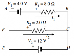
Figure-1
Now let’s mark both ends of every resistor with $+$ and $-$ that help in identifying the voltage drops and peaks. We know that the direction of conventional current is always from a higher potential to a lower potential.
Applying Kirchoff’s voltage rule to the loop $ABCF$:
\[V_1+I_2R_2=I_1R_1\]
Similarly, for the other loop $FCDE$:
\[V_2=I_2R_2\]
Solving this equation for $I_2$ gives us:
\[I_2=\dfrac{V_2}{R_2}\]
\[=\dfrac{12 V}{2.0\Omega}\]
\[I_2=6.0\space A\]
Since $I_2$ is a positive value, the current in $R_2$ goes as shown in the figure. Now solving the first equation for $I_1$:
\[I_1=\dfrac{V_1+I_2R_2}{R_1}\]
Substituting $I_2=V_2/R_2$:
\[I_1=\dfrac{V_1+\dfrac{V_2}{R_2}R_2}{R_1}\]
\[I_1=\dfrac{V_1+V_2}{R_1}\]
\[I_1=\dfrac{4.0 V+12 V}{8.0}\]
\[I_1=2.0\space A\]
Since $I_1$ also comes out to be a positive value, the current in the resistor $R_1$ goes as shown in the figure.
Numerical Result
$I_2=6.0\space A$ is a positive value, and the current in the resistor $R_2$ goes from left to right.
$I_1= 2.0\space A$ also comes out to be a positive value, so the current in the resistor $R_1$ goes from left to right.
Example
A $60.0\Omega$ resistor is in parallel with a $120\Omega$ resistor. This parallel connection is in series with a $20.2\Omega$ resistor connected across a $15.0 V$ battery. Find the current and the power supplied to the $120\Omega$.
The current in the $120.0\Omega$ resistor is $I_{120} = \dfrac{V_{AB}}{120.0}$, but the equivalent resistance $R_{AB}$ is:
\[\dfrac{1}{R_{AB}}=\dfrac{1}{60.0}+\dfrac{1}{120.0} = 40.0\Omega\]
This resistance of $40.0\Omega$ is in series with the $20.0\Omega$, thus total Resistance is $40.0\Omega+20.0\Omega=60.0\Omega$. Using ohm’s law, the total current from the battery is:
\[I=\dfrac{15.0V}{60.0\Omega}=0.250\space A\]
Now for $V_{AB}$:
\[V_{AB}=(0.250A)R_{AB}=0.250\times40.0=10.0\space V\]
Finally, the current from $120.0\Omega$ is:
\[I_{120}=\dfrac{10.0}{120.0}=8.33\times 10^{-2}\space A\]
And the power delivered is:
\[P=I_{120}^{2}R=(8.33\times 10^{-2})^2(120.0)=0.833\space W\]
Images/Mathematical drawings are created with Geogebra.