
This problem aims to familiarize us with different circuital laws and circuit analysis. The concepts required to solve this problem are related to Kirchoff’s circuit laws, which include Kirchoff’s first law, known as the current law, and Kirchoff’s second law, known as the voltage law.
In circuit analysis, Kirchhoff’s circuit laws help to form an equation for respective components such as a resistor, capacitor, or inductor. Now according to Kirchoff’s first law, the total charge entering a junction (also known as a node) is equal to the total charge exiting the junction since no charge is wasted.
Let’s say the currents
According to Kirchoff’s second law, the voltage of a closed loop is equal to the sum of every potential decline in that loop, which equals zero.
Expert Answer
To start the solution, we will be using Kirchhoff’s loop rule. We shall start by drawing a current via each resistor. This step basically shows the directions preferred for the currents. These chosen directions are random, and if found to be incorrect, then the negative value of the calculated current will indicate that the analysis was the opposite.
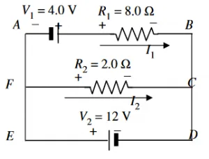
Figure-1
Now let’s mark both ends of every resistor with
Applying Kirchoff’s voltage rule to the loop
Similarly, for the other loop
Solving this equation for
Since
Substituting
Since
Numerical Result
Example
A
The current in the
This resistance of
Now for
Finally, the current from
And the power delivered is:
Images/Mathematical drawings are created with Geogebra.