From the given Figure, answer the questions either True or False based on the circuit’s behavior:
– After the RELAY is switched to either the N.O. (“normally open”) or N.C. (“normally closed”) state, the transient response of the circuit is for the short time.
– In this experiment, the transient current flow has an exponential decay to zero.
– The charge Q of the capacitor decay exponentially when the relay move to the N. O. state.
– The capacitor charge Q decreases during current I is positive.
– The negative voltage measured in VOLTAGE IN 2 is due to positive current I.
– VOLTAGE IN 1 is measured to be positive when the charge Q on the capacitor is positive.
– The given quantity t1/2=? ln 2 is the half-life of an exponential decay, where ?= R.C. is the time constant in an R.C. circuit. The current in a discharging R.C. circuit drops by half whenever t increases by $t_{12}$. For a circuit with $R=2k\Omega$ and $C=3uF$, if at t=5 ms the current is 6 mA, find the time (in ms) that the current of 3 mA would be.
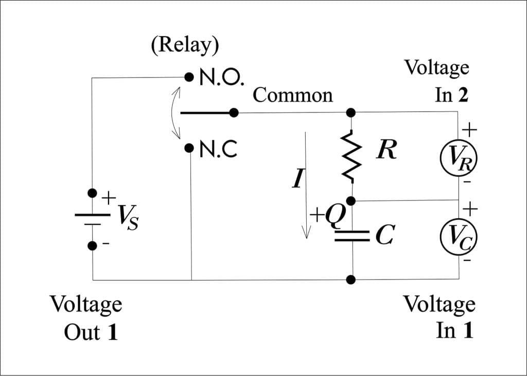
Figure 1
This question aims to find the current, charge, and voltage in the RC circuit. There are multiple statements given and the task is to find the correct one.
Moreover, this question is based on the concepts of physics. In the RC circuit, the capacitor is charged when it is connected to the source. However, when the source is disconnected, the capacitor discharges through the resistor.
Expert Answer
1) As the capacitor is initially uncharged, it resists the change in voltage instantaneously. Hence,
Voltage, when the switch is closed the initial current,
\[ i =\dfrac{V_s}{R} \]
So, the statement is true.
2) At any instant the current is:
\[ i =\dfrac{(V_s – V_c)}{R} \]
Furthermore, the increase in voltage causes the $i=0$, therefore:
\[ V_c = V_s \]
So, the statement is true.
3) When $V_s$ is connected, the voltage across a capacitor increases exponentially till it reaches a steady state. Therefore, the charge is:
\[q = CV_s\]
So, the statement is false.
4) The direction of current shown in the figure prove that the charge in the capacitor is increasing.
So, the statement is false.
5) The voltage across the capacitor and the resistor is positive, therefore, Voltage IN 2 will be positive.
So, the statement is false.
6) According to Kirchoff voltage law, Voltage OUT 1 and Voltage IN 1 are equal.
So, the statement is false.
7) The capacitor’s current equation is:
\[I(t) = \dfrac{V_s}{R}[1 -\exp(-t/RC)]\]
Since,
$I=6mA$
$t=5ms$
Therefore,
\[\dfrac{V_s}{R}=10.6mA\]
\[3 mA = 10.6 mA [1 – \exp(-t/(2k\Omega \times 3uF) )]\]
\[\Rightarrow t=2ms\]
Numerical Results
\[t=2ms\]
Example
When the current through a 10k\Omega resistor is 5mA, find the voltage against it.
Solution:
The voltage can be found as:
\[V = IR = 5mA \times 10k\Omega\]
\[V = 50V\]
Images/Mathematical are created with Geogebra.