JUMP TO TOPIC
Plans are the set of diagrams not only restricted to the top view. But it is usually used for the top view. Figure 1 shows a plan view of an object.
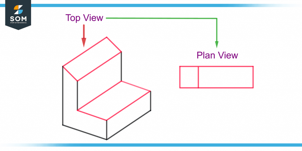
Figure 1 – Demonstration of Plan View of an Object
Use of Plan in Various Types of Fields
The plan view plays an important role in many types of architectural fields, such as landscape architecture and urban architecture. It is also used in engineering fields such as civil engineering, system engineering, mechanical engineering, and industrial engineering.
Purpose of Plan
A plan is used for technical purposes in engineering, architecture, and planning. The geometric features of a building, site, component, or product are accurately captured with the help of plan views. These are detailed versions that can be used for orientation and presentation purposes.
The main purpose of a plan is to portray a design for an object or place to convey complete information to a manufacturer or a builder.
Technical Drawing
A technical drawing refers to the process and the skill of producing plans or designs. A type of technical drawing is the “working drawing,” which is a document used to build the product.
The data required to manufacture an engineering product are its angles and dimensions in the working drawing. Figure 2 shows the dimensions of an object.
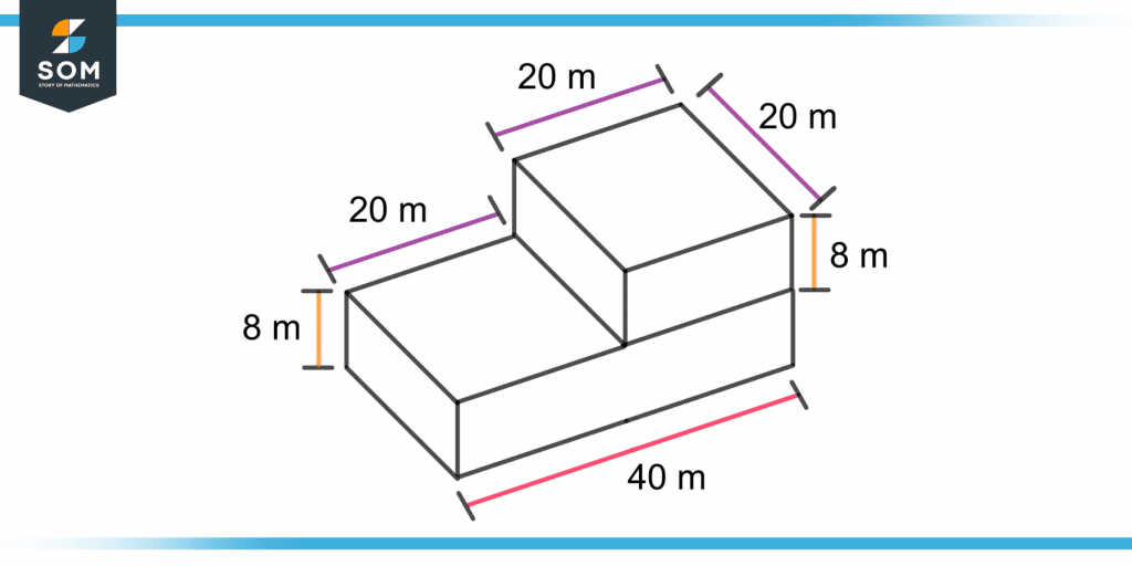
Figure 2 – Demonstration of Dimensions of an Object
Different Features of Plan
The main features of a plan view include its scale and its format.
Scale
A scale is defined as the relative ratio of all the dimensions of the actual building or object. A plan is drawn as a scale drawing in which a specific ratio is set relative to the original size of the building or object.
Different scales can be used for different scale drawings. The types of scale include the engineering scale, the architect scale, and the metric scale.
The metric scale is mostly used when drawing plans. The scale ratios used in the metric system are 1:10, 1:100, 1:1000, 1:5, 1:50, 1:500, 1:5000, 1:20, 1:200, and 1:2000. The ratios 1:360 and 1:240 are often used to draw site views.
Format
A plan format of a building or product includes a set of plan views. Remember the word “plan” can be used for all kinds of views including the top view.
Plans are also known as the “bluelines” or “blueprints”. The format excludes all unnecessary views and contains all the necessary information required for the plan set.
Other Types of Views
A multi-view projection is viewing the object or building from different angles. Other than the plan(top) view, the multi-view projection includes the section view and the elevation view. These three types of view depict different projections on the horizontal or vertical plane and are discussed below.
Section
A section view is a 2-D diagram of a building drawn by slicing through it at a specific cutting plane. This view can be of the full building or a section of the building.
Imagine cutting a building or an object vertically and standing right in front to view it. Figure 3 shows a section drawing of an object.
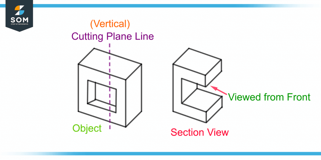
Figure 3 – Demonstration of Section View of an Object
Section design is a common drawing used in architectural and engineering fields for the internal graphic representation of a vertical cross-section of a building or a device. A type of section is the blow-up section or section callout.
Like plans, the section drawing is also an orthographic projection but with a different perspective.
Elevation
An elevation is also known as the “side view.” Unlike the section view, the elevation view is from the exterior of the building. It is a two-dimensional diagram drawn from the sides of a building or object. Figure 4 shows an elevation drawing of an object.
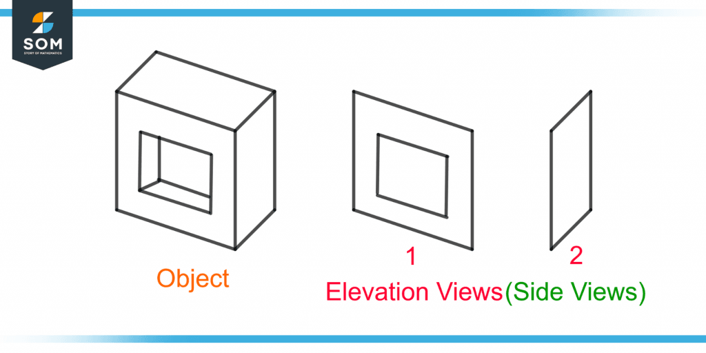
Figure 2 – Demonstration of the Elevation Views of an Object
The types of elevation drawings include the elevation detail and the elevation call-out.
Different Types of Plan
The various types of plan diagrams are illustrated below.
Roof Plan
As the name suggests, a roof plan is the plan view of the roof of a building. It demonstrates the top of a building including the stair bulkheads, roof equipment, parapets, and the roof layout.
Site Plan
A site plan is the top view of a complete site with different buildings. It shows the entire site including the proper lines, landscape, building locations, roads, and utilities. The roof plan is a small part of the site plan.
A site plan can also be drawn by cutting a building’s first floor with a horizontal cutting plane and viewing the site from above. This is known as the first-floor site plan.
Reflected Ceiling Plan
The Reflected Ceiling Plan, also known as RCP, is the reflected mirror image of the ceiling when a mirror is placed on the ground and the ceiling image is viewed from the top. The RCP depicts the ceiling height, lighting, and ceiling structure.
Perspective Plan
A perspective plan view only shows the idea or perspective of how the building will look and does not focus on its construction.
Detailed Plan
A detailed plan consists of all the factors, such as the material used and connections made for the construction of a building. A plan view is used for a detailed plan as it is used for large-scale projects.
Additional Plan Drawings for Complex Systems
The complex and large-scale projects consist of the following additional plans.
Electrical Drawings
Electrical drawings include lighting, power connection, cable layout, equipment, signal and communication systems, and a local area network.
Structural Drawings
Structural drawings portray the complete structural details of the building. A large-scale project can have many sheets that depict only its structure.
Mechanical Drawings
A mechanical drawing consists of air conditioning and heating systems, plumbing, fire protection, and ventilation systems.
Example
Figure 5 shows an object. Draw the plan view of this object.
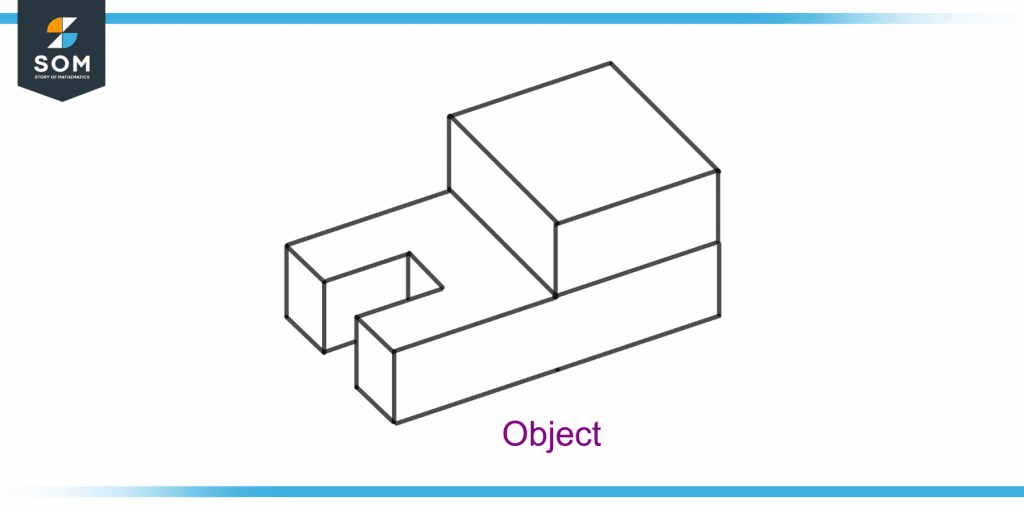
Figure 5 – A Given Object whose Plan View is Required
Solution
Figure 6 shows the plan view of the given object.
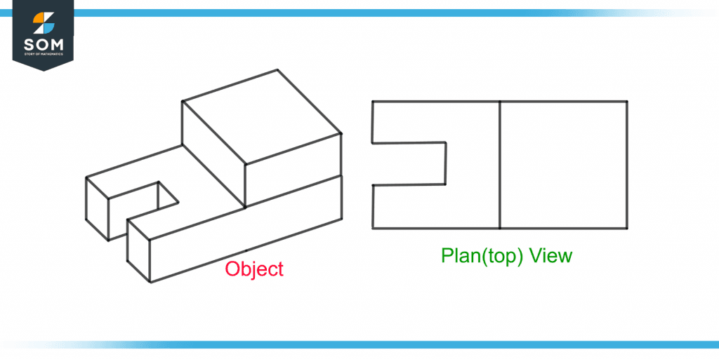
Figure 6 – A Plan View of the Given Object
All the images are created using GeoGebra.